What kind of camera is best for laser beam characterization – cmos vs ccd
Laser beam profiling is an important part of laser research, development, and production, providing critical information about the quality and performance of laser beams. One of the key components of a laser beam profiler is the camera used to capture images of the laser beam. However, not all cameras are created equal when it comes to laser beam characterization. In this article, we will explore the different types of cameras available for laser beam profiling, and discuss the key factors to consider when choosing a camera for your laser beam characterization needs. By understanding the advantages and limitations of each camera type, you can make an informed decision about which camera is best suited for your specific application, and ensure the most accurate and reliable results from your laser beam profiling system.
When it comes to characterizing laser beams, there are several types of cameras that can be used, each with its own advantages and disadvantages. Some of the most common types of cameras used for laser beam characterization include:
CCD Cameras (Charge-Coupled Device): These are cameras that use a CCD sensor to capture images. CCD cameras are sensitive to a wide range of wavelengths and are capable of capturing high-resolution images. They also have low noise, high dynamic range, and good color reproduction. CCD cameras are commonly used in laser beam profiling and other types of beam characterization.
CMOS Cameras (Complementary Metal-Oxide-Semiconductor): These cameras use a CMOS sensor to capture images. CMOS cameras have similar capabilities as CCD cameras but are more cost-effective, have lower power consumption, and can be built in smaller form factors. They are also useful for fast imaging and high-speed applications.
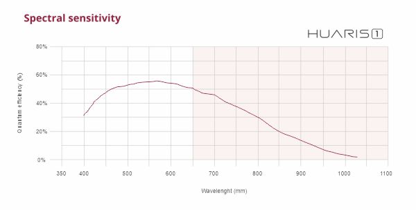
The spectral sensitivity curve of HUARIS ONE profiler is presented in the graph below:
The spectral sensitivity curve of HUARIS ONE profiler
ICCD Cameras (Intensified Charge-Coupled Device): These cameras use a CCD sensor and an image intensifier to capture images. ICCD cameras are sensitive to low-light conditions and can be used to capture images of laser beams with very high power. They are commonly used in high-power laser applications, such as laser cutting and welding.
InGaAs Cameras: These are cameras that use a InGaAs sensor, a specific type of sensor that is sensitive to the near-infrared (NIR) wavelengths, which is a common region for laser applications. These cameras can be useful for measuring high-power beams in the NIR region, and are commonly used in fiber-optic communication, spectroscopy and other related applications.
SWIR cameras (shortwave infrared): These cameras are sensitive to the shortwave infrared (SWIR) wavelengths, which is another common region for laser applications. These cameras are useful for measuring high-power beams in the SWIR region, and are commonly used in sensing and imaging applications.
The best camera for laser beam characterization will depend on the specific requirements of the application, such as wavelength, power, and spatial resolution of the laser beam, as well as the environment the camera will be used in. It’s important to consider factors such as cost, size, and ease of use when selecting a camera for laser beam characterization.
CMOS vs. CCD - what is best?
CMOS (Complementary Metal-Oxide-Semiconductor) and CCD (Charge-Coupled Device) are two different types of image sensors that can be used in cameras, including those used for laser beam characterization. Both types of sensors have their own advantages and disadvantages, and the choice between them will depend on the specific requirements of the application.
CCD sensors are known for their high image quality and low noise, they are sensitive to a wide range of wavelengths and are capable of capturing high-resolution images. CCDs are also capable of capturing high dynamic range images, and have good color reproduction. They are commonly used in scientific and industrial applications where high image quality is needed. However, CCDs are generally more expensive than CMOS sensors and have higher power consumption.
CMOS sensors, on the other hand, are more cost-effective than CCDs and have lower power consumption. They can also be built in smaller form factors, making them more suitable for portable or compact applications. They are also useful for fast imaging and high-speed applications, and their technology allows for more integration on chip, such as the addition of a processing unit that can reduce the need for external components. However, CMOS sensors can have higher noise levels and lower quantum efficiency (QE) than CCDs, which means they may require additional processing to achieve similar image quality as CCDs.
In summary, CCDs are better suited for applications that require high image quality, while CMOS sensors are better suited for cost-sensitive applications or those that require low power consumption and compact form factor.
As for the use in the laser applications, CMOS arrays are believed to have higher damage threshold than CCDs.
It’s worth noting that the choice between CMOS and CCD sensors is not always clear cut, and it’s important to consider the specific requirements of the application, such as wavelength, power, spatial resolution and data rate, as well as other factors such as cost, size, and ease of use.
Check the specification of Huaris laser beam profilers
When it comes to selecting a detector array for laser beam characterization, there are several options available, including black and white (monochrome) arrays, and color arrays. The choice between them will depend on the specific requirements of the application.
Black and white detector arrays are sensitive from ultraviolet, through visible to near-infrared (NIR) spectrum spectral area. They are commonly used in laser beam profiling and other types of beam characterization, as they can provide high spatial resolution and good sensitivity. They are less affected by ambient light and can be more sensitive to the laser radiation.
Color detector arrays, on the other hand, are sensitive to multiple wavelengths of light at a time, typically in the visible spectrum, and can capture information about the color of the light. They are commonly used in applications where color information is important, such as in color imaging, material analysis, and color sensing. They can provide more information about the laser beam but can be more affected by ambient light. On the other hand, they have poorer spatial resolution, for this reason they are hardly used in the laser beam characterization where demand for high accuracy of the intensity mapping is crucial.
The choice between a black and white detector array or a color detector array will depend on the specific requirements of the application. If the color information is not important for the application, a black and white detector array can provide a better sensitivity and spatial resolution, while if color information is important a color detector array should be used. Additionally, the environment where the detector will be used should be taken into consideration, as color detector array can be more affected by ambient light.
Color depth and analog-digital converter
When it comes to color detector arrays, the color depth and the analog-digital converter (ADC) used in the camera can affect the overall image quality and the ability to accurately measure the laser beam.
Color depth, also known as bit depth, refers to the number of bits used to represent the color of each pixel in an image. The higher the color depth, the more colors can be represented, and the more accurate the color representation will be. A higher color depth also allows for a greater dynamic range, which is the range of brightness levels that can be captured in an image. A higher dynamic range allows for more accurate measurements of the laser beam.
Analog-digital converter (ADC) is a circuit that converts an analog signal into a digital representation of that signal. The ADC in a camera converts the analog image signal captured by the sensor into a digital image. The ADC resolution, measured in bits, determines the maximum number of digital values that can be produced by the converter. A higher ADC resolution will result in a higher color depth, which allows for more accurate color representation and dynamic range.
The color depth and ADC resolution of a camera will affect the ability to accurately measure the laser beam. A higher color depth and ADC resolution will provide more accurate color representation and dynamic range, which allows for more accurate measurements of the laser beam.
It’s worth noting that the color depth and ADC resolution are not the only factors that affect the image quality and measurement accuracy, other factors such as the sensor quality, the lens, and the optics also play a role.
Pixel size and pixel pitch - what is the difference?
Pixel size and pixel pitch are two related but distinct characteristics of image sensors, such as those used in cameras for laser beam characterization.
Pixel size refers to the physical size of each individual pixel on the image sensor. It is typically measured in micrometers (µm) and can range from a few micrometers for high-resolution sensors to tens of micrometers for lower resolution sensors. A larger pixel size generally means that each pixel can collect more light, which can result in higher sensitivity and a higher signal-to-noise ratio (SNR).
Pixel pitch, on the other hand, refers to the distance between the centers of adjacent pixels on the image sensor. It is typically also measured in micrometers (µm) and can range from a few micrometers for high-resolution sensors to tens of micrometers for lower resolution sensors. Pixel pitch is inversely proportional to the resolution of the sensor, meaning that a smaller pixel pitch results in a higher resolution sensor, and vice-versa.
Finer pixel size allows fitting a greater number of pixels in a given physical area allowing increase of an array effective resolution.
In summary, pixel size and pixel pitch are related but distinct characteristics of image sensors. Pixel size refers to the physical size of each pixel and can affect the sensitivity and SNR of the sensor. Pixel pitch refers to the distance between adjacent pixels and can affect the resolution of the sensor.
Both pixel size and pixel pitch are important characteristics to consider when selecting an image sensor for a specific application, and the best choice will depend on the specific requirements of the application, such as the resolution, sensitivity, and dynamic range needed.
As a general conclusion, where spatial resolution is more important than smaller pixel size should be selected. On the other hand, when sensitivity is critical, then the greater pixels will perform better.
Huaris One products are designed for higher sensitivity. Their pixel size is 5.2 micron. While for applications where higher spatial resolutions required the Huaris Five will be an optimal choice with their 2.2 micron pixel size.
Optical size of a detector array
The optical size of a detector array is a parameter of, so called, clear aperture. I.e. it refers to the overall dimensions of the detector array which is sensitive to light. In general greater size of the detector arrays is desired; however, the greater size of the detector implies greater price. For this reason an optimal selection has to be made.
Huaris One have detector area of: 6.656 mm x 5.325 mm while Huaris Five have the size of: 5.702 mm x 4.277 mm.
In laser systems, there are several types of connectors that are commonly used for different purposes. The choice of connector standard will depend on the specific requirements of the application and the type of signals being transmitted. Some of the most common connector standards used in laser systems include:
USB (Universal Serial Bus): This is a widely used connector standard that is commonly used to transmit data and power between devices. USB connectors are commonly used to connect laser diode drivers, controllers, and other peripheral devices to a laser system.
USB standard also defines various editions: 2, 3, 3.1, etc. The key difference between them is the transmission speed and maximum length of a cable.
Ethernet: This is a networking standard that is commonly used to transmit data between devices. Ethernet connectors are commonly used to connect laser systems to a network or the internet, allowing for remote control and monitoring of the laser system.
RS-232: This is a serial communication standard that is commonly used to transmit data between devices. RS-232 connectors are commonly used to connect laser systems to controllers and other peripheral devices.
GPIB (General Purpose Interface Bus): This is a standard for connecting electronic instruments to computers and controllers. GPIB connectors are commonly used to connect laser systems to controllers and other peripheral devices.
HDMI (High-Definition Multimedia Interface): This is a digital interface standard that is commonly used to transmit video and audio data between devices. HDMI connectors are commonly used to connect laser systems to displays and other video output devices.
Fiber Optic connectors are also commonly used in laser systems for high power or high-speed data transmission, as they can provide high-bandwidth and immunity to electromagnetic interference (EMI).
It’s worth noting that the choice of connector standard will depend on the specific requirements of the application and the type of signals being transmitted. Some detectors may use multiple connector standards to transmit different types of signals.
Moreover, the selection of a transmission standard has to be made at the device design stage to match the amount of the data that needs to be transmitted by an interface in a unit of time. For this reason, e.g. using a USB 3 standard in the application where the amount of data is not significant is a non-optimal decision.
Type of shutter
In laser systems, a shutter is a device that is used to control the exposure of the laser beam, either by opening or closing the beam path. There are several types of shutters that are commonly used in laser systems, each with their own advantages and disadvantages. Some of the most common types of shutters used in laser systems include:
Mechanical Shutters
These are shutters that use mechanical means, such as a blade or a diaphragm, to block or allow the passage of the laser beam. Mechanical shutters are typically reliable, durable, and can handle high-power laser beams, but can be relatively slow to open and close, and may introduce vibrations.
Acousto-Optic Shutters
These are shutters that use the principle of acousto-optics, where an acoustic wave is used to deflect or scatter the laser beam, to block or allow the passage of the laser beam. Acousto-optic shutters are fast, highly precise, and can handle high-power laser beams, but are relatively expensive and can be sensitive to temperature changes.
Electro-Optic Shutters
These are shutters that use the principle of electro-optics, where an electric field is used to change the refractive index of a material and affect the passage of the laser beam, to block or allow the passage of the laser beam. Electro-optic shutters are fast, highly precise, and can handle high-power laser beams, but are relatively expensive and can be sensitive to temperature changes.
AOM (Acousto-Optical Modulator)
This type of shutter uses the principle of acousto-optics, but instead of deflecting or scattering the laser beam, they modulate the intensity of the beam. AOM’s are fast, precise and can handle high-power laser beams, but they also can be relatively expensive and sensitive to temperature changes.
Pockels cells
This type of shutter uses the Pockels effect, where an electric field is applied to a crystal to change the refractive index of the crystal, which in turn modulates the transmission of the laser beam. Pockels cells are fast, precise and can handle high-power laser beams, but they also can be relatively expensive and sensitive to temperature changes.
The choice of shutter will depend on the specific requirements of the application, such as the laser beam power, repetition rate, speed, and precision. Additionally, the environment in which the laser system will be operated, such as temperature range and vibration should be considered when selecting the shutter.
The term “shutter” is also used to refer to the readout mode in the detector arrays. The “global” shutter is a method where the image is captured by a full array at a time and then, in one go it is transferred to the processing electronics. On the other hand an expression “rolling shutter” refers to the situation when a portion of an image is transferred to the electronics and in the second step consecutively a second portion of image is transferred to the electronics. Global shutter is a preferred solution with smaller arrays and in the applications where the very fast phenomena are observed. On the other hand, when the image does not change very rapidly and the camera has a greater array, the rolling shutter is used to allow greater data transfers.